Remote Power Switches
Being able to turn a vacuum cleaner or fan on and off from across a room can make life much easier while working on a project. I had previously made an extension cord which incorporated a double lightswitch and had found that I was dragging that box around with the switch and the vacuum cleaner power cord plugged in, and that was getting awkward. So I created a dedicated "remote" switch power cable to make it easier to use.
I'm going to show four designs for such a remote switch. One of them is a reasonable design. Three of them add functionality, but also introduce hazards, and therefore I must recommend against them. But I find those interesting enough to explore.
All components use NEMA5-15 receptacles and plugs.
Basic Remote Switch
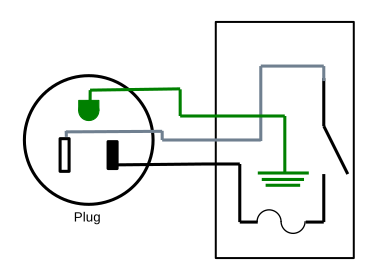
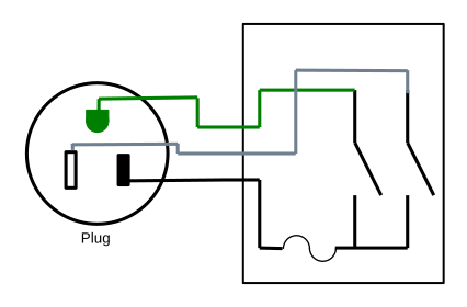
Beginning with the simplest design, we have a switch that controls a receptacle:
Complete parts list:
| Part | Qty |
|---|---|
| single-width deep electrical box | 2 |
| electrical box outlet cover plate | 1 |
| electrical box switch cover plate | 1 |
| conduit clamp grommet | 3 |
| heavy-duty extension cord | 1 |
| NEMA5-15 power outlet | 1 |
| light switch | 1 |
| fuse holder | 1 |
| fuse | 1 |
| wire nut | 1 |
| 10-12 AWG insulated female spade crimp terminal | 2 |
| 4-5" of stranded wire | 1 |
Cut the extension cord so you have the plug end connected to about 2 feet of wire, then cut the receptacle off the other part of the extension cord. This will give you a pigtail that can plug into a receptacle, and a length of power cable.
To create a hole in which to mount the fuse holder in the switch module, drill/dremel a hole of matching size in the electrical box knock-out plate opposite the knock-out plate removed for the power cable.
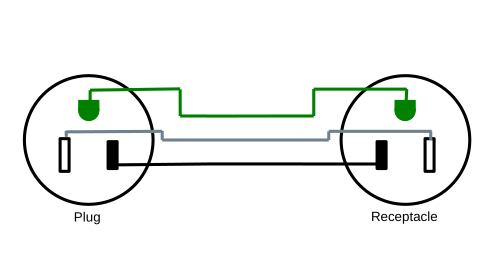
Wire the contraption up following the diagram above. The pigtail with the plug is wired to the receptical in the box, The wire nut is used inside the receptacle box to connect the hot wire from the pigtail to the hot wire in the power cable. The power cable runs from the receptacle box to the switch box. The power cable hot wire connects to the fuse holder in the switch box with a crimp terminal, and then the other lead on the fuse holder connects to the switch using a crimp terminal and the short length of stranded wire. The ground wire connects to the ground terminal on the switch.
Be sure to use a multimeter to check that your wiring is correct and you have not introduced a short before you plug it into power.
This is the reasonable design; it gives you a switch that controls a power outlet up to some number of feet away, depending on the size of the extension cord you started with. It solves the problem at hand. If you're here looking to solve that problem, this is the design to use, and you can skip the rest of the blog post. The remaining designs below, while more functional, introduce hazards that I cannot recommend.
But if you have an engineering mindset, come with me as I explore them anyway.
Extensible Remote Switch
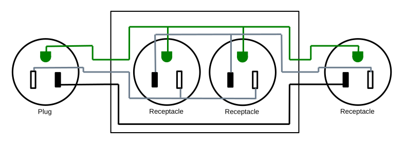
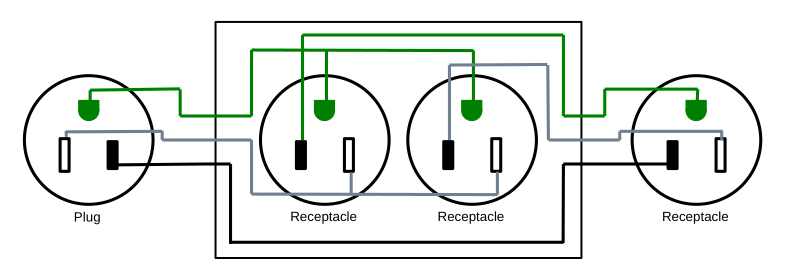
The above design is quite functional, but you have to commit to the distance between the receptacle and the switch. We can add a receptacle and plug into the design between the two like this:
And now you can put a standard extension cord of almost arbitrary length between the receptacle box and the switch.
But this also introduces a hazard. Now the switch is its own module, and could accidentally be plugged into a regular power outlet and flipped "on", directly creating a short circuit. While doing so should throw a breaker or blow the fuse in the switch module, there is risk of problems, so I recommend against building this.
Complete parts list:
| Part | Qty |
|---|---|
| single-width deep electrical box | 2 |
| electrical box outlet cover plate | 1 |
| electrical box switch cover plate | 1 |
| conduit clamp grommet | 3 |
| heavy-duty extension cord | 1 |
| NEMA5-15 power outlet | 1 |
| light switch | 1 |
| fuse holder | 1 |
| fuse | 1 |
| wire nut | 1 |
| NEMA5-15 receptacle | 1 |
| NEMA5-15 plug | 2 |
| 10-12 AWG insulated female spade crimp terminal | 2 |
| 4-5" of stranded wire | 1 |
For this design, you make a different set of cuts on the power cord. Cut the extension cord so you have the plug end connected to about 2 feet of wire. From the other portion of the extension cord, cut two 2-foot lengths from the cut end to give you two 2-foot sections of power cable, with the remainder of the power cable still connected to the original receptacle.
Build a (shorter) extension cord:
Sub-assembly parts list:
| Part | Qty |
|---|---|
| heavy-duty extension cord receptacle + wire | 1 |
| NEMA5-15 plug | 1 |
Wire one of the plugs to the remaining part of the extension cord (which has the extension cord's original receptacle on it) to give you a (shortened) extension cord.
Build the receptacle module:
Sub-assembly parts list:
| Part | Qty |
|---|---|
| single-width deep electrical box | 1 |
| electrical box outlet cover plate | 1 |
| conduit clamp grommet | 2 |
| heavy-duty extension cord plug + 2' wire | 1 |
| heavy-duty extension cord 2' wire | 1 |
| NEMA5-15 power outlet | 1 |
| wire nut | 1 |
| NEMA5-15 receptacle | 1 |
The wire nut is used inside the receptacle box to connect the hot wire from the short plug pigtail to the hot wire going to the receptacle.
Build the switch box module:
Sub-assembly parts list:
| Part | Qty |
|---|---|
| single-width deep electrical box | 1 |
| electrical box switch cover plate | 1 |
| conduit clamp grommet | 1 |
| heavy-duty extension cord 2' wire | 1 |
| light switch | 1 |
| fuse holder | 1 |
| fuse | 1 |
| NEMA5-15 plug | 1 |
| 10-12 AWG insulated female spade crimp terminal | 2 |
| 4-5" of stranded wire | 1 |
Be sure to use a multimeter to check that your wiring is correct and you have not introduced a short before you plug any of this into power.
Double Remote Switch
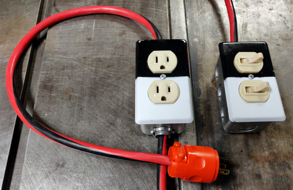
A different functionality enhancement is to make the two receptacles in the receptical box independent of each other and put two switches in the control box, giving two controls in one device.
This also introduces a hazard, though a more subtle one; in this case we use the ground wire between the receptacle box and the control box to carry load current. The ground wire may be a smaller gauge wire than the neutral and hot conductors, and thus risk overheating. Additionally, the control box which you will be handling is no longer grounded; if something goes wrong electrically, you risk electrocution.
| Part | Qty |
|---|---|
| single-width deep electrical box | 2 |
| electrical box cover plate | 2 |
| conduit clamp grommet | 3 |
| heavy-duty extension cord | 1 |
| NEMA5-15 power outlet | 1 |
| double light switch | 1 |
| fuse holder | 1 |
| fuse | 1 |
| spray paint, white | 1 |
| spray paint, black | 1 |
| wire nut | 1 |
| 10-12 AWG insulated female spade crimp terminal | 2 |
| 4-5" of stranded wire | 1 |
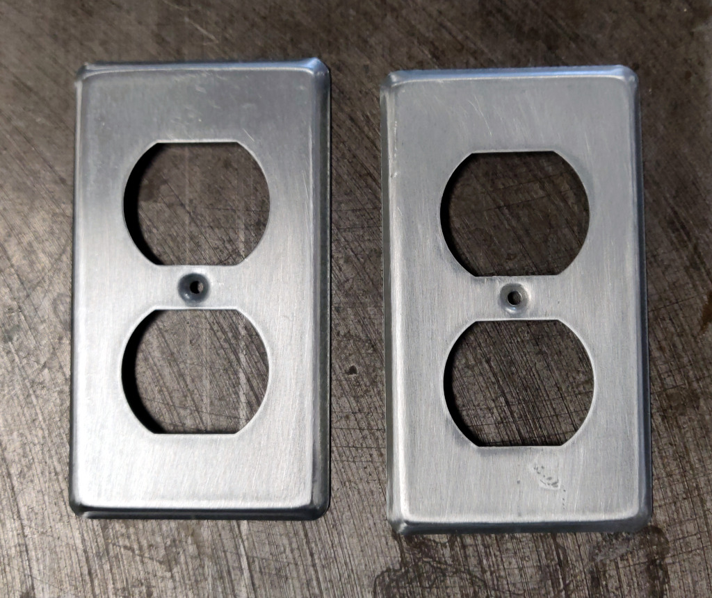
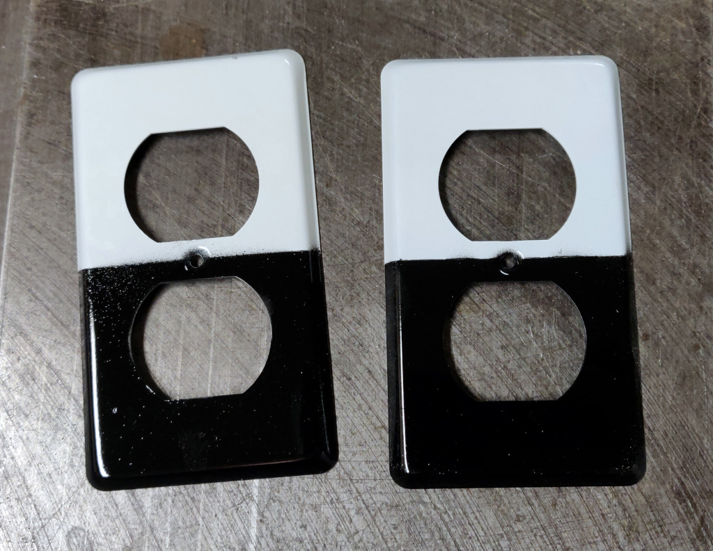
Lightly sand the faceplates,
and paint one half white and one half black.
For this design, you make the same cuts in the extension cord as for the single remote switch design. Cut the extension cord so you have the plug end connected to about 2 feet of wire, then cut the receptacle off the other part of the extension cord. This will give you a pigtail that can plug into a receptacle, and a length of power cable.
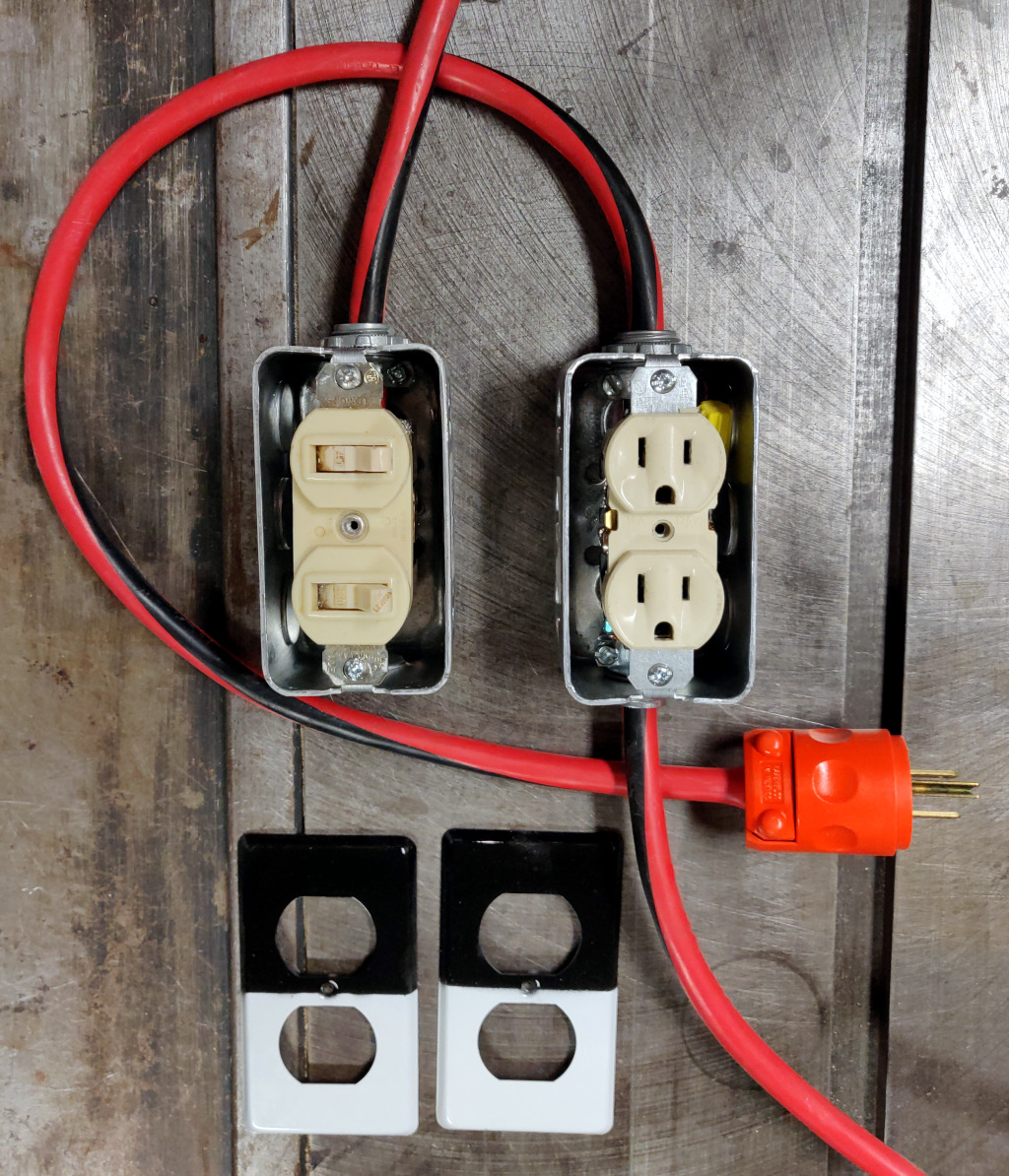
Wire the contraption up following the diagram above. The wire nut is used to connect the hot wire inside the receptacle box.
Note that you will likely need to snap off a metal tab connecting the hot terminals of the receptacles to make them independently controllable.
Be sure to use a multimeter to check that your wiring is correct and you have not introduced a short before you plug it into power.
Once the painted faceplates have dried, install them so that the white switch controls the white receptacle, and the black switch controls the black receptacle.
Double Extensible Remote Switch
The two previous enhancements can be combined to yield the most functional, but also the most hazardous version of this remote power switch:
| Part | Qty |
|---|---|
| single-width deep electrical box | 2 |
| electrical box cover plate | 2 |
| conduit clamp grommet | 3 |
| heavy-duty extension cord | 1 |
| NEMA5-15 power outlet | 1 |
| double light switch | 1 |
| fuse holder | 1 |
| fuse | 1 |
| spray paint, white | 1 |
| spray paint, black | 1 |
| wire nut | 1 |
| NEMA5-15 receptacle | 1 |
| NEMA5-15 plug | 2 |
| 10-12 AWG insulated female spade crimp terminal | 2 |
| 4-5" of stranded wire | 1 |
Paint the faceplates as for the previous build.
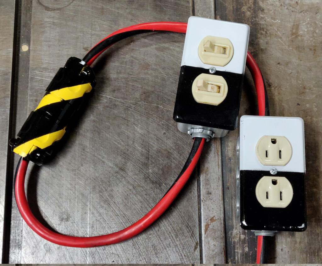
In an effort to mitigate one of the hazards of this design, I took the plug and receptacle in the middle of this system and painted them to make them stand out as somehow different from normal plugs and receptacles. Before building everything, I plugged them into each other and wrapped two pieces of electrical tape around them in a spiral to create something resembling a warning stripe. Since they were yellow plastic, I sprayed them with black paint, then removed the electrical tape. That gave a visually striking touch to those connectors:
For this design, you make the same cuts in the extension cord as for the single extensible remote switch design. Cut the extension cord so you have the plug end connected to about 2 feet of wire. From the other portion of the extension cord, cut two 2-foot lengths from the cut end to give you two 2-foot sections of power cable, with the remainder of the power cable still connected to the original receptacle.
Build a (shorter) extension cord:
Sub-assembly parts list:
| Part | Qty |
|---|---|
| heavy-duty extension cord receptacle + wire | 1 |
| NEMA5-15 plug | 1 |
Wire one of the plugs to the remaining part of the extension cord (which has the extension cord's original receptacle on it) to give you a (shortened) extension cord.
Build the receptacle module:
Sub-assembly parts list:
| Part | Qty |
|---|---|
| single-width deep electrical box | 1 |
| electrical box outlet cover plate | 1 |
| conduit clamp grommet | 2 |
| heavy-duty extension cord plug + 2' wire | 1 |
| heavy-duty extension cord 2' wire | 1 |
| NEMA5-15 power outlet | 1 |
| wire nut | 1 |
| NEMA5-15 receptacle | 1 |
The wire nut is used inside the receptacle box to connect the hot wire from the short plug pigtail to the hot wire going to the receptacle.
Note that you will likely need to snap off a metal tab connecting the hot terminals of the receptacles to make them independently controllable.
Build the switch box module:
Sub-assembly parts list:
| Part | Qty |
|---|---|
| single-width deep electrical box | 1 |
| electrical box outlet cover plate | 1 |
| conduit clamp grommet | 1 |
| heavy-duty extension cord 2' wire | 1 |
| double light switch | 1 |
| fuse holder | 1 |
| fuse | 1 |
| NEMA5-15 plug | 1 |
| 10-12 AWG insulated female spade crimp terminal | 2 |
| 4-5" of stranded wire | 1 |
Be sure to use a multimeter to check that your wiring is correct and you have not introduced a short before you plug any of this into power.
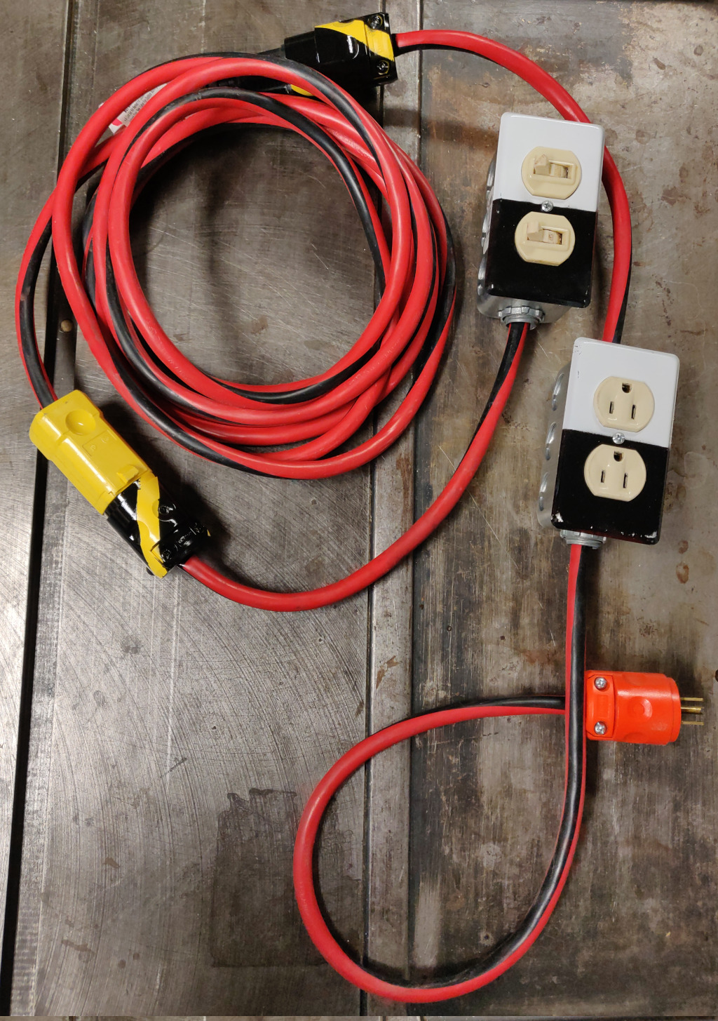
And here is the completed contraption in all its hazardous glory:
(A couple of notes regarding the photo: I started with an extension cord on which I had previously replaced the original receptacle. Further, I made my cuts "backward" from what is described here; I used the plug end of the original extension cord for the build of the shortened extension cord. I've attempted to refine the designs given here based on my trial-and-error build experience.)
Conclusion
As always, the above should be used at your own risk, but hopefully you can see that there are risks and weigh them appropriately. And once again, the simplest answer is frequently the best answer.

 rss
rss


