Lego and aluminum phone camera tripod mount
For a family project, we needed a way to take pictures with the stability of a tripod. The best camera we own happens to be the one in a OnePlus 6 cellphone. We have a collapsible tripod with a standard mounting plate and bolt.
Those don't exactly attach to each other.
Ok, so how can we approach this? Well, the tripod has a 1/4" 20tpi captured bolt. So we need something rigid for it to screw into. I can drill and tap some aluminum to meet that interface. For holding the OnePlus 6, a frame built from Lego could work.
So all we need then is something that can bolt onto the tripod, and to which we can attach Lego pieces.
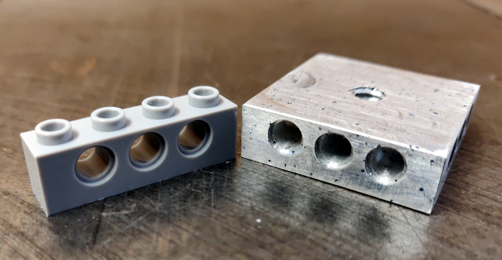
Studs look challenging to machine, and I expect they would be extremely finicky to get machined precisely enough to give the right amount of "clutch". And might be prone to damaging bricks, which we want to avoid. An easier approach is to drill holes compatible with Lego Technic pins.
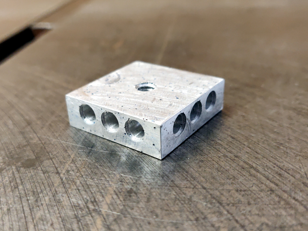
The tripod attachment plate is roughly 4 studs by 6 studs in size. So a 4x4 brick with a 1/4" 20-tpi hole in the center, with no studs, and with Technic pin holes around the edge should give us a very versatile base from which to work.
For material, I started from an aluminum ingot I had cast from cans, and machined that using my CNC mill (a Grizzly G8689 mini-mill with a HeavyMetal CNC conversion kit).
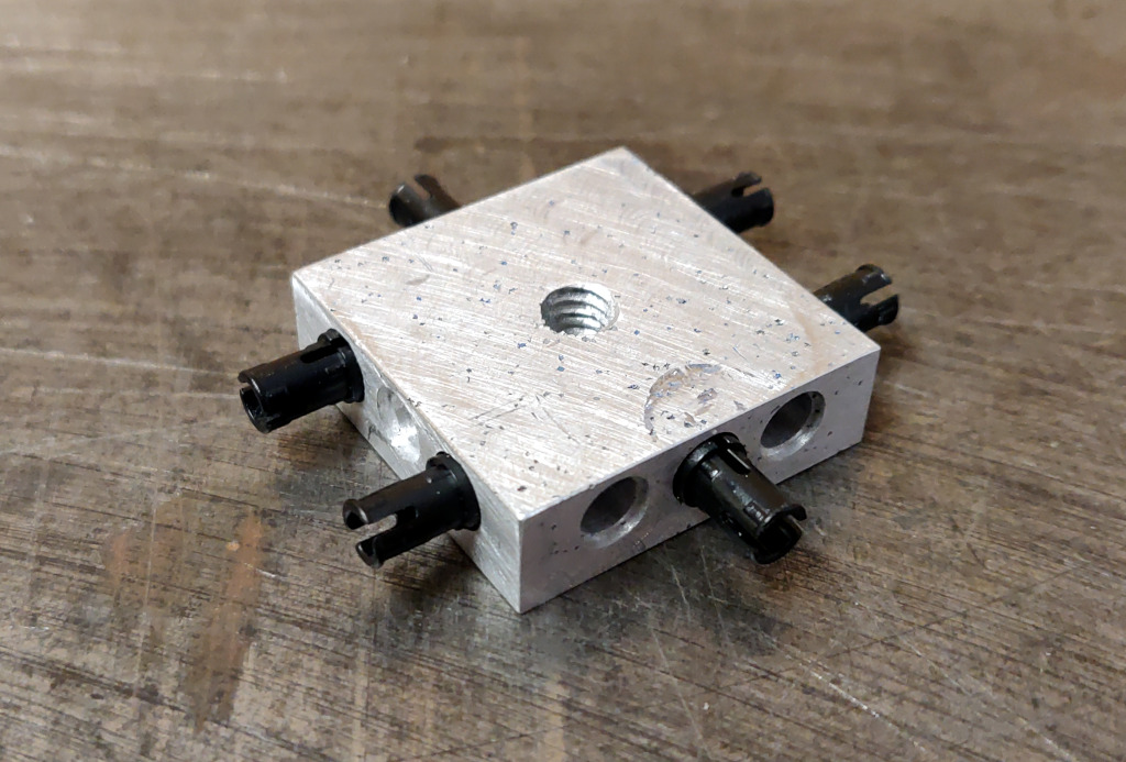
To start, I machined an aluminum block 1.254" x 1.254" x 0.380". (Ok, fine, the actual part was off by 2 thou, but it was close enough for the task at hand.) Then I machined 3 Technic pin holes on each of the 4 sides of the part. That included the shoulder around the top of each hole. I used an 1/8" endmill, and machined the outer ring, then the main hole within that. For each of those operations, I helixed down to cut the body of the hole, then cut the bottom circle to get a flat bottom. I don't have the g-code I actually used handy, but this gcode file gives the basic idea. Of note, the two Technic pin holes at each corner overlap partially within the part, so only one Technic hole at each corner can be used at a time. I then drilled a 13/64" hole through the center of the square face of the part, and threaded the hole with a 1/4" 20-tpi tap.
(There are many readily-visible flaws in the part. The casting had a lot of porosity, the edge of the tapped hole is rough, and there are some ugly machining marks on part of it. That said, they have not impaired its functionality.)
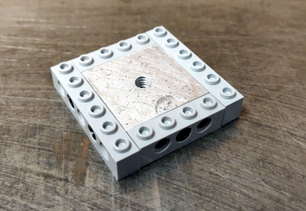
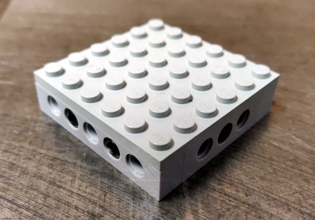
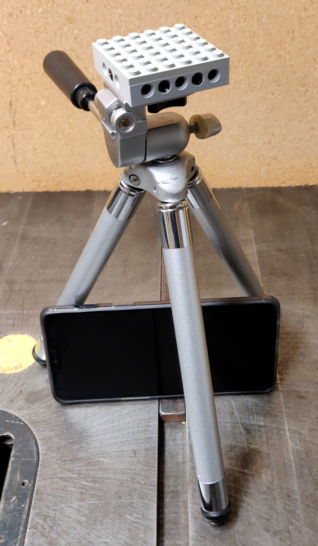
Once I verified that the part accepted Technic pins, and screwed down solidly on the tripod, I wrapped the part in Technic bricks and slapped a 6x6 plate on top of it. That gets us a Lego-compatible tripod.
I then handed the contraption and a OnePlus 6 to my oldest son, Samuel, with directions to design and build a way to mount the phone on the tripod.
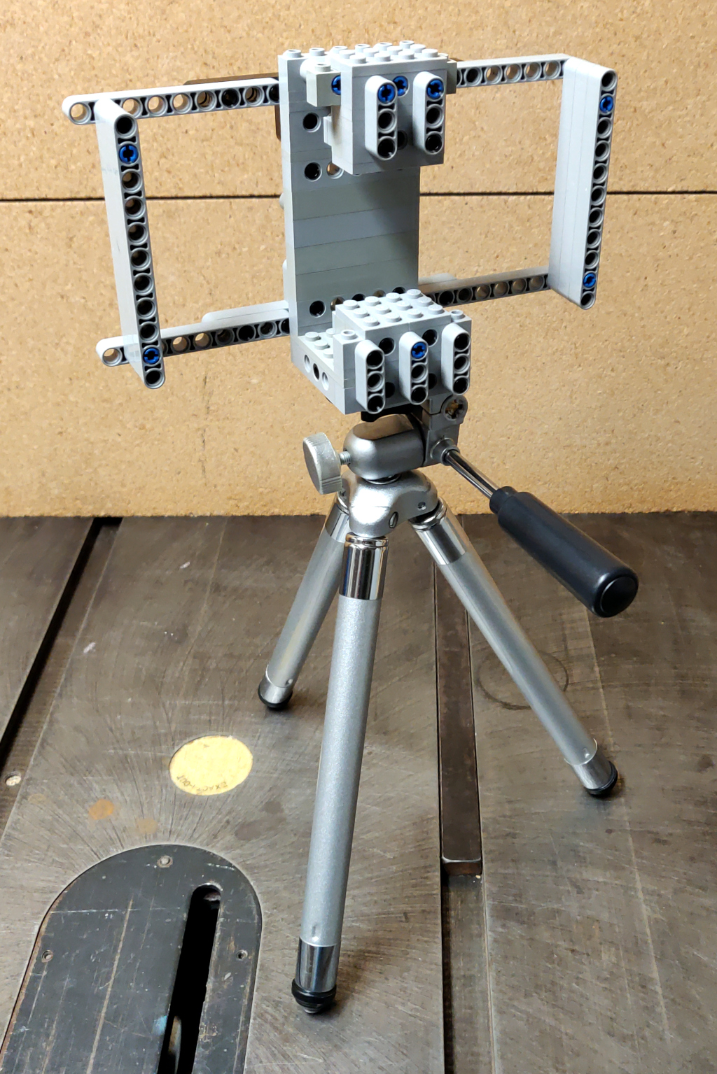
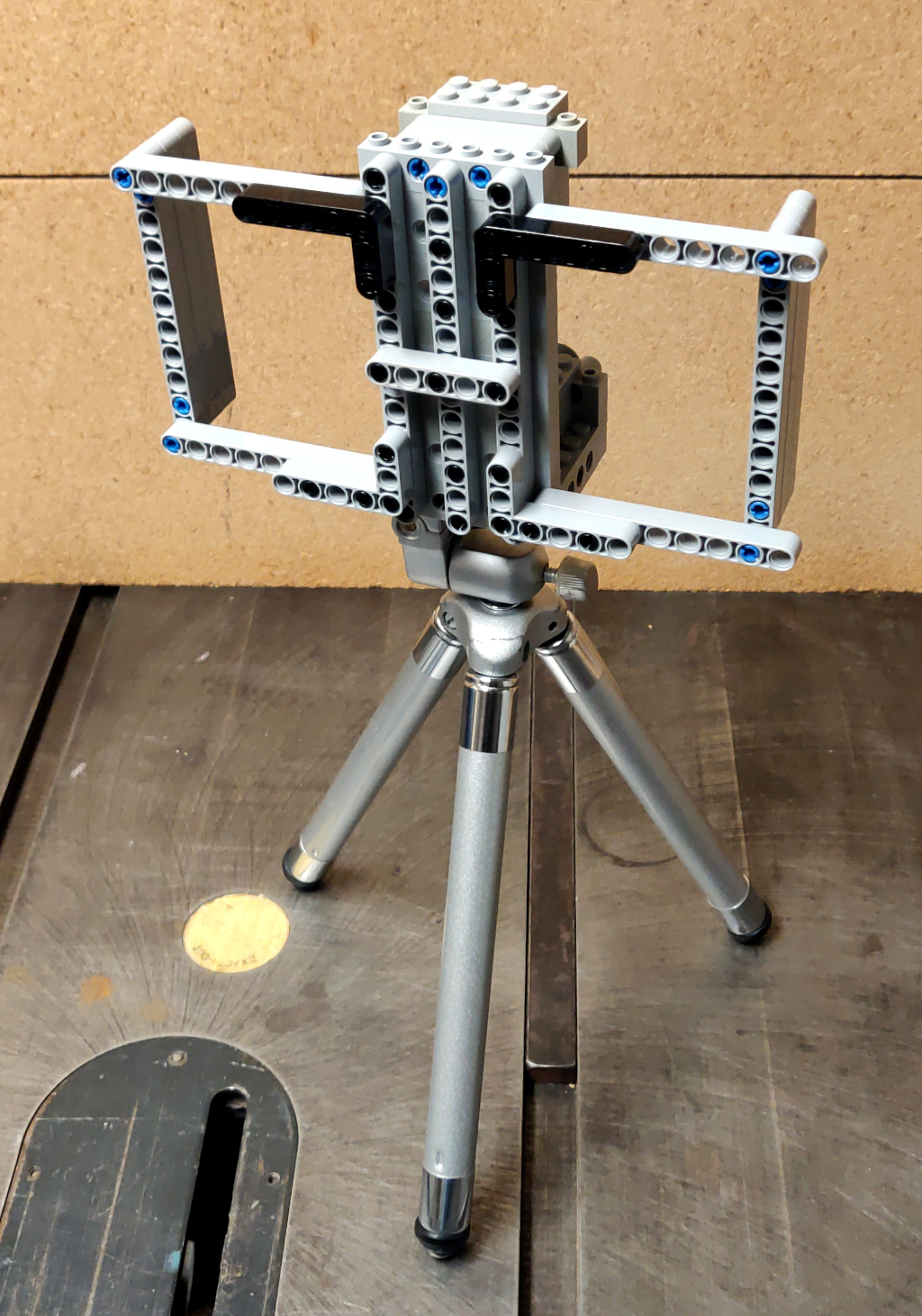
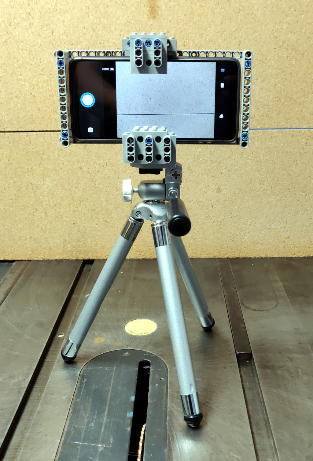
In short order, he came back with this:
While there is room for refinement and optimizing the part count, this thing is very solidly built and did the job well.
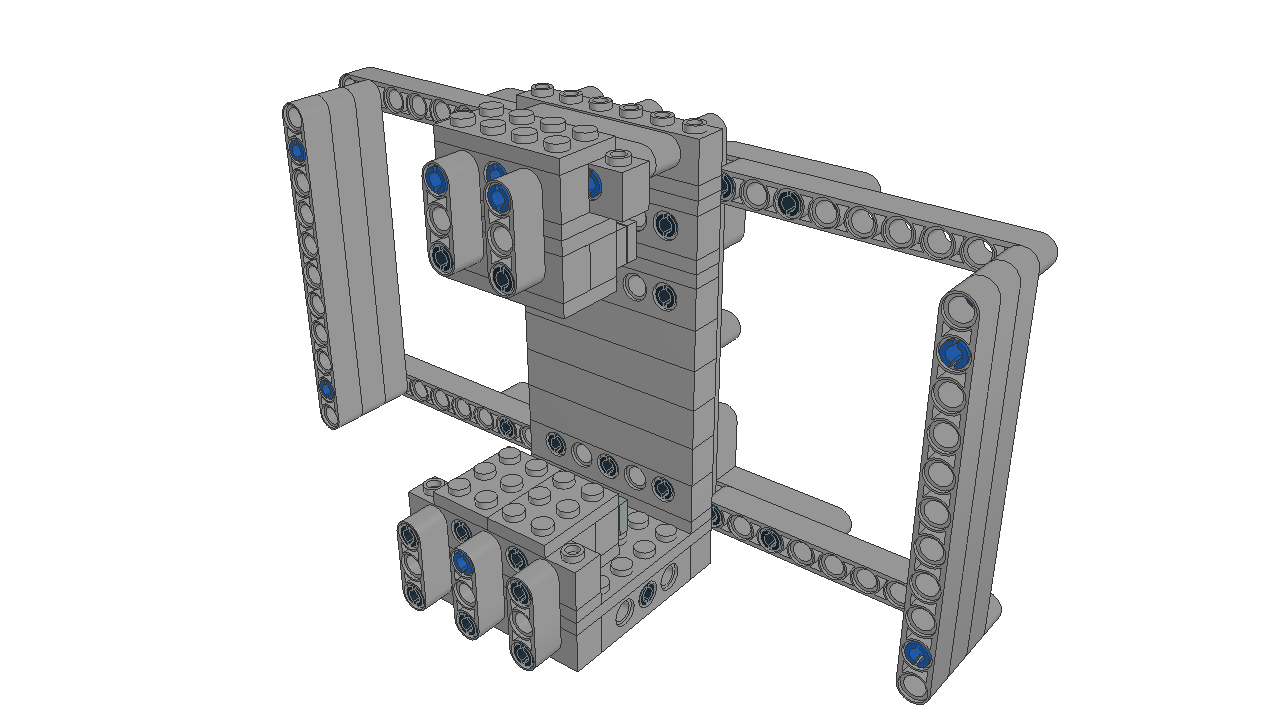
Using LeoCAD, I modeled the Lego portion of the contraption,
And I created build instructions using LPub3D for anyone looking to build their own.
Based on the success of this, I expect that the next time I need to interface between Lego and "the real world", I will use the same 4x4 Technic-compatible brick design and drill-and-tap holes to suit the need.
Blinds Tilt Mechanism Repair
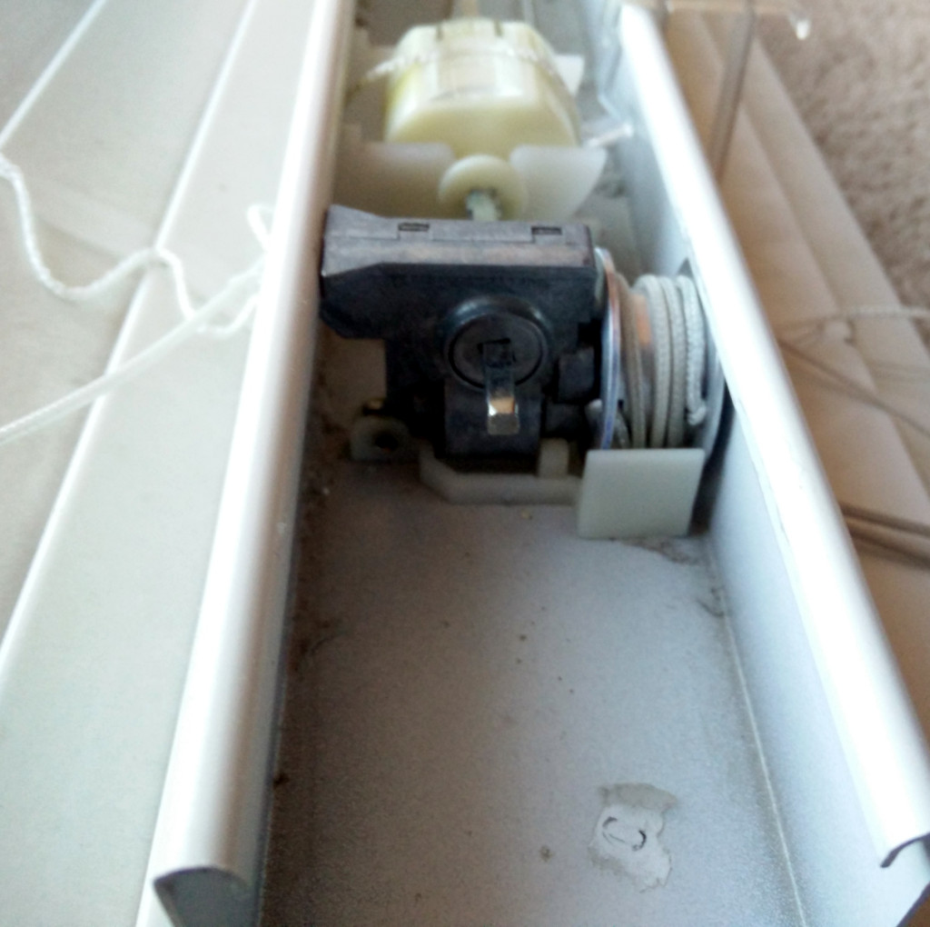
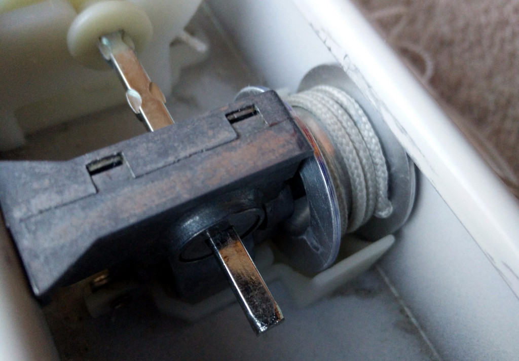
We have a large faux-wood blind on our dining room window. The window pane itself is 70"x70"; which makes for a great view. However, the tilt mechanism stopped working in fairly short order. The tilt mechanism uses a pull-cord based mechanism which is no longer offered in blinds. I replaced the mechanism the first time it failed, but when it failed the second time in much the same way, I could no longer find a replacement for the parts. The original mechanism failed because the interface between the cord spool and the shaft driving the worm gear which drove the tilting of the blinds had worn, become loose, and allowed the cord spool to rotate without turning the worm gear shaft. The replacement mechanism failed in a different place; it had a bushing to adapt the sqare rod that runs the length of the blinds to a hexagonal through-hole in the driving gear. That bushing was made of plastic and had worn to the point that the drive gear could rotate without rotating the square rod.
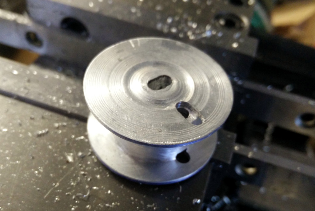
The original tilt mechanism was made largely from metal components, while the replacement I had purchased was largely plastic. Examining them both, I determined that it would be more straight-forward to machine a new pully for the original mechanism than to machine a drive gear for the replacement mechanism. The original pully was made of nylon; I chose to machine a replacement pully from aluminum bar stock.
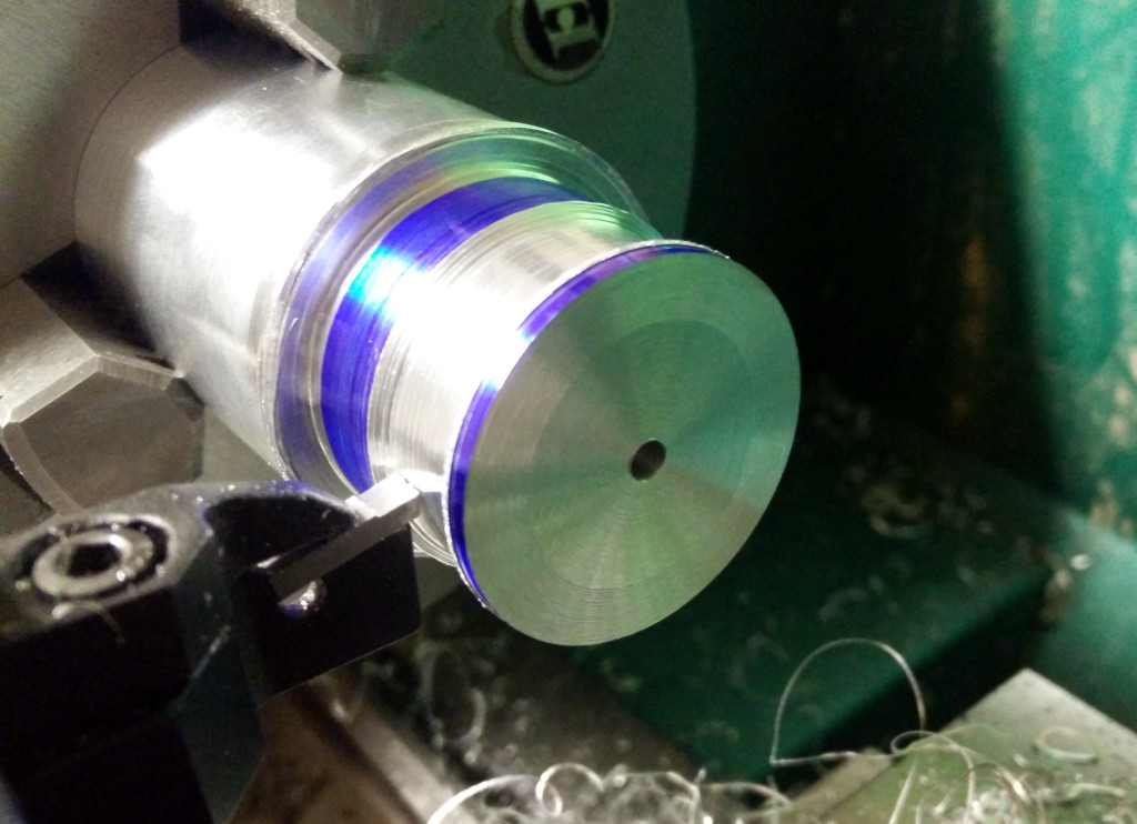
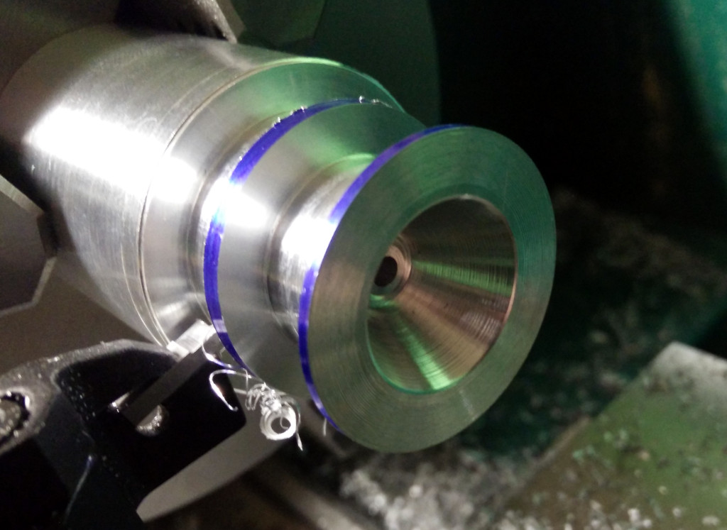
Cutting the main profile of the spool body:
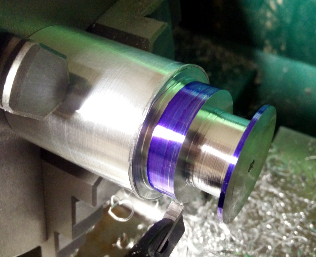
And the conical recess in the spool:
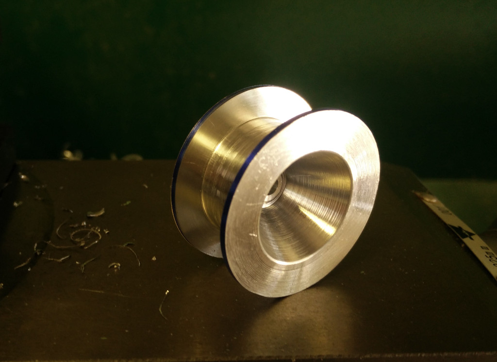
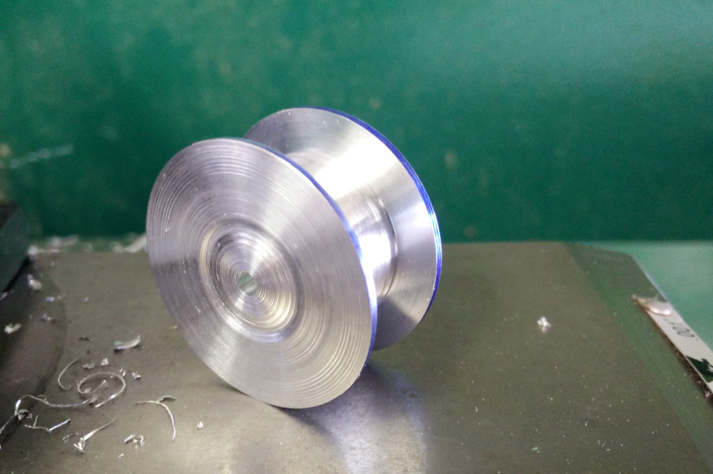
Cutting the spool off the stock:
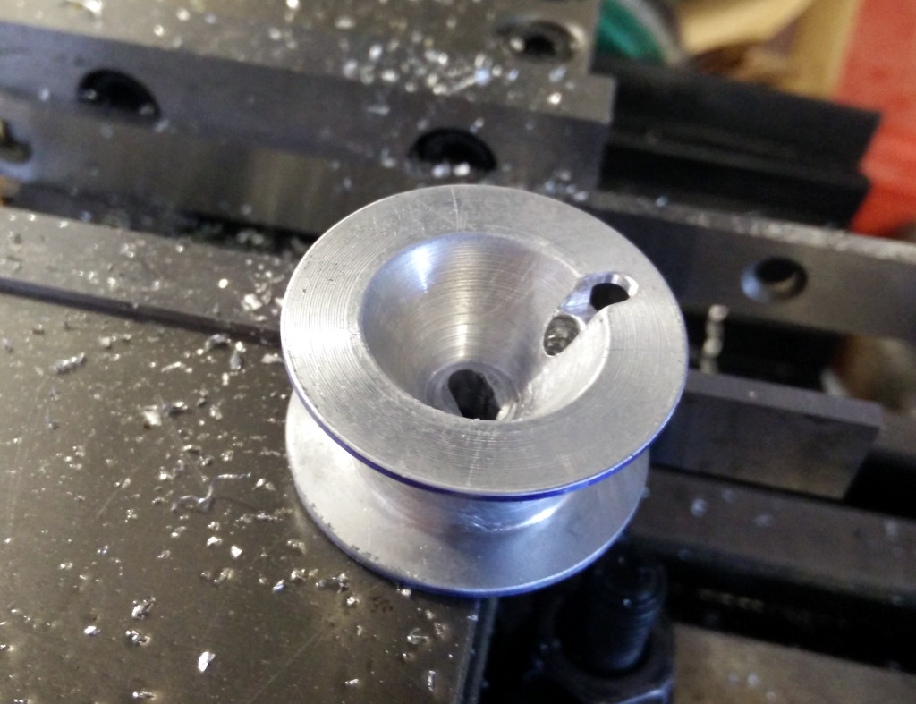
Milled the slot for the worm gear shaft and the holes required for the threading the pull cord through:
Installed in the blinds:
This has held up well over the past 8 months, and it was gratifying to be able to repair something when replacement parts were no longer available.
Making Stake Pocket Anchors
I bought a toolbox for my pickup truck, and needed to mount it to the bed rails securely. Using some J-hooks to bolt it to the metal inside the stake pockets did not work well enough; the loaded toolbox shifted from side to side while driving, scraping up the bed rail covers in the process. I needed a more secure mounting option for the toolbox that did not require drilling holes in my truck, and if I could avoid drilling holes in the toolbox, even better. Oh, and I needed to get it done immediately to avoid additional damage. While Magnum Manufacturing offers the stake pocket tie downs they use for their headache racks, I needed to solve the problem immediately, not wait for a well-made product to arrive.
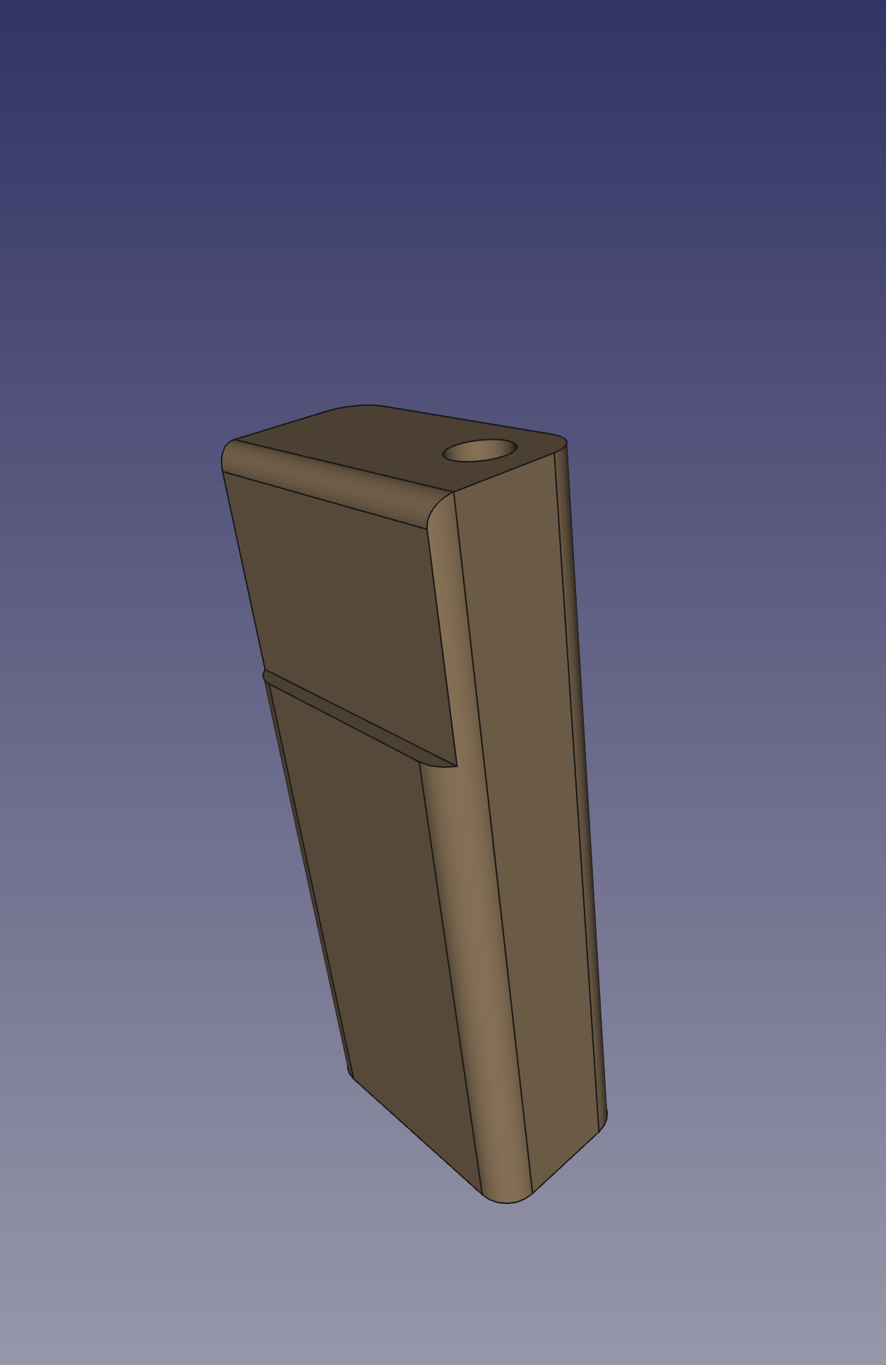
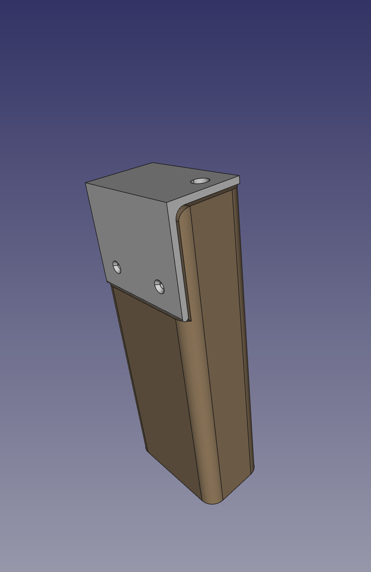
The concept is to have an assembly that fits into the stake pocket which I can bolt onto from the top, and fasten from the side. My solution was to cut some scrap 2x4 down to fill the stake pocket, and cut out space for a bracket, and a recess for the bolt.
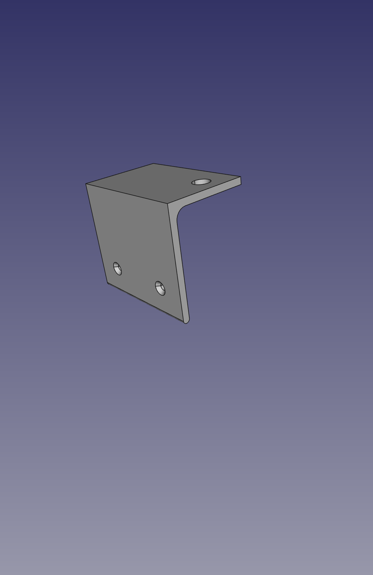
I fabricated the bracket from 1/8"-thick 2x2" angle iron; cutting it to size, drilling counter-sunk holes for the screws, and tapping a hole for a bolt on top.
I drilled pilot holes in the wood block and assembled the anchors with exterior wood screws:
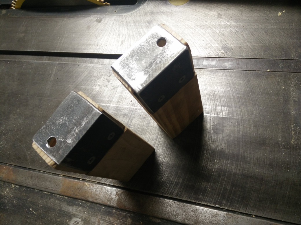
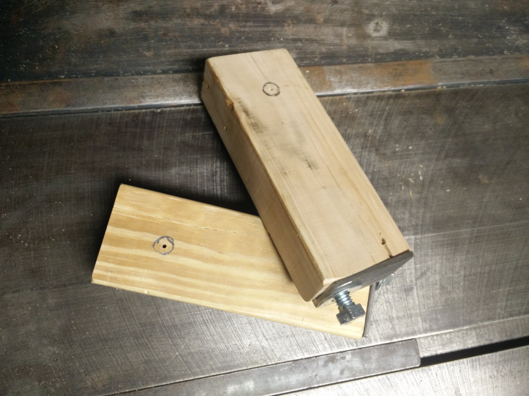
Given that I was in a hurry and making it up as I went along, the actual anchors looked a bit more like this:
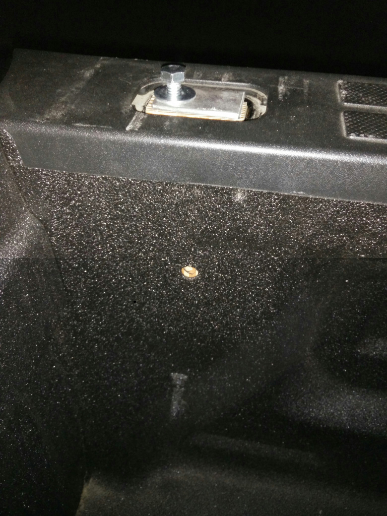
I dropped the anchors into the stake pockets and marked the location of the hole inside the truck bed, then drilled a pilot hole in the center of that.
Installing the anchors in the truck meant dropping the anchor in place
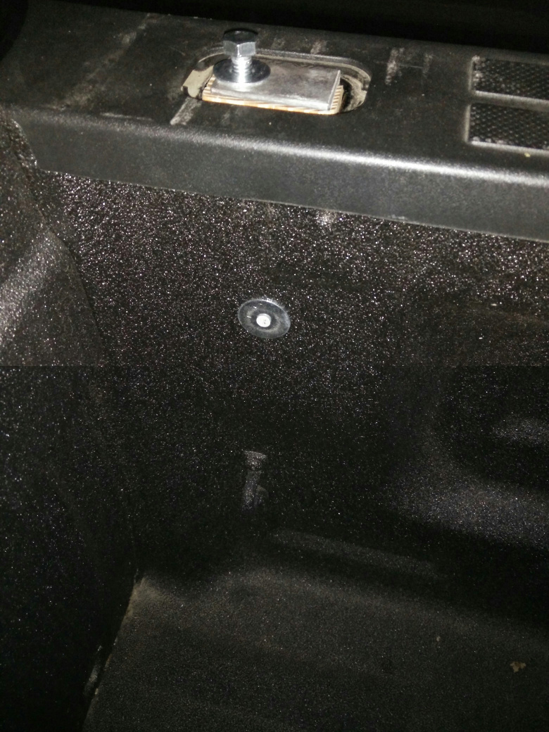
and securing it with an exterior wood screw and fender washer.
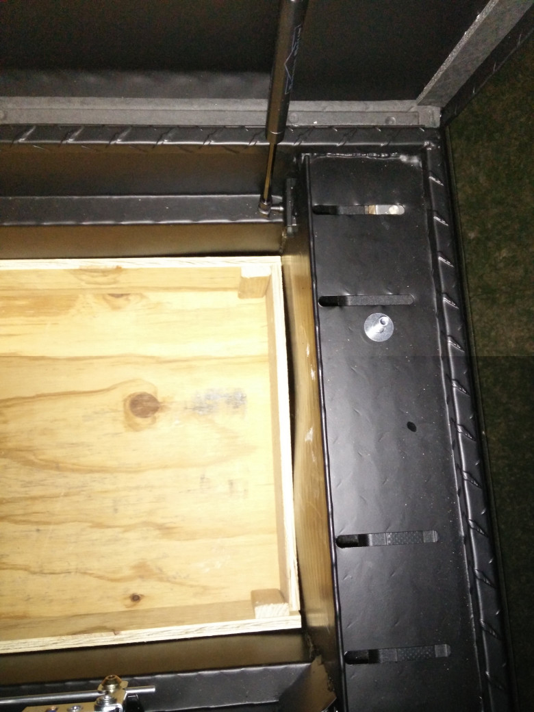
From there, it was a matter of lining up the toolbox slot with the bolt hole
and bolting it down.
Now, the toolbox is much more solidly anchored to the truck.

 rss
rss
